Description
PD Series
Essentially, PD Series Cable Diagnostic System consists of the following units:
- VLF hipot tester (optional)
- High voltage filter
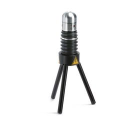
- Coupling capacitor
- B2 Suite® software for diagnostics and reporting
As with VLF cable testing, a sinusoidal 0.1 Hz VLF (very low frequency) voltage is used for measurement of partial discharge.
These systems are available for 4 different voltage ranges – 34 kV peak, 62 kV peak, 90 kV peak, 120 kV and 200 kV peak.
Fields of application
Measurement of partial discharge is applicable for cables and accessories of medium voltage networks with various insulation materials:
- XLPE
- PE
- PILC
Moreover, assessment of the following plant is possible:
- Rotating machines
- Transformers
- Gas-insulated switchgear (GIS)
Measurement of partial discharge and its levels
The PC based software serves for display and analysis of measurement results. The intensity of partial discharge is measured in pico Coulomb (pC) and displayed versus time. By means of fully automatic analysis of the reflectograms collected during the measurement – via a method referred to as time-domain reflectometry TDR – a location of insulation irregularities is possible and they are displayed in a partial discharge mapping format.
A phase-related depiction of the partial discharges provides additional information, useful for the evaluation of the device under test.
In a report all relevant measurement values are recorded:
- Calibration Pulse (in accordance with IEC 60270) and end detection
- Background noise of the measurement arrangement
- Partial-discharge inception voltage (PDIV)
- Partial-discharge level at 1.7 Uo
- Partial-discharge extinction voltage (PDEV)
Datasheet
CHARACTERISTICS
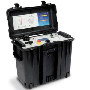
COMPACT AND PORTABLE
Our TD and PD systems have been designed for maximum portability and on-site use. This makes them utilizable for versatile applications, e.g. off-shore.
SIMULTANEOUS TD AND PD MEASUREMENT
Included (or extendable) diagnostics units allow parallel measurement of TD and PD levels, resulting in significant time savings and preventing negative influence on the results of a second test carried out due to feeding high test voltages during the first test.
TRUE MODULARITY
All our high voltage cable test sets can be easily extended to any HVA test set, with corresponding voltage range, to a complete diagnostics system. This keeps the initial investment low.